- 您现在的位置:买卖IC网 > Sheet目录839 > AU016D104KAG2A (AVX Corporation)CAP CER 0.1UF 6.3V 10% 0201
�� �
�
�Surface� Mounting� Guide�
�MLC� Chip� Capacitors�
�COMMON� CAUSES� OF�
�MECHANICAL� CRACKING�
�The� most� common� source� for� mechanical� stress� is� board�
�depanelization� equipment,� such� as� manual� breakapart,� v-�
�cutters� and� shear� presses.� Improperly� aligned� or� dull� cutters�
�may� cause� torqueing� of� the� PCB� resulting� in� flex� stresses�
�being� transmitted� to� components� near� the� board� edge.�
�Another� common� source� of� flexural� stress� is� contact� during�
�parametric� testing� when� test� points� are� probed.� If� the� PCB�
�is� allowed� to� flex� during� the� test� cycle,� nearby� ceramic�
�capacitors� may� be� broken.�
�A� third� common� source� is� board� to� board� connections� at�
�vertical� connectors� where� cables� or� other� PCBs� are�
�connected� to� the� PCB.� If� the� board� is� not� supported� during�
�the� plug/unplug� cycle,� it� may� flex� and� cause� damage� to�
�nearby� components.�
�Special� care� should� also� be� taken� when� handling� large� (>6"�
�on� a� side)� PCBs� since� they� more� easily� flex� or� warp� than�
�smaller� boards.�
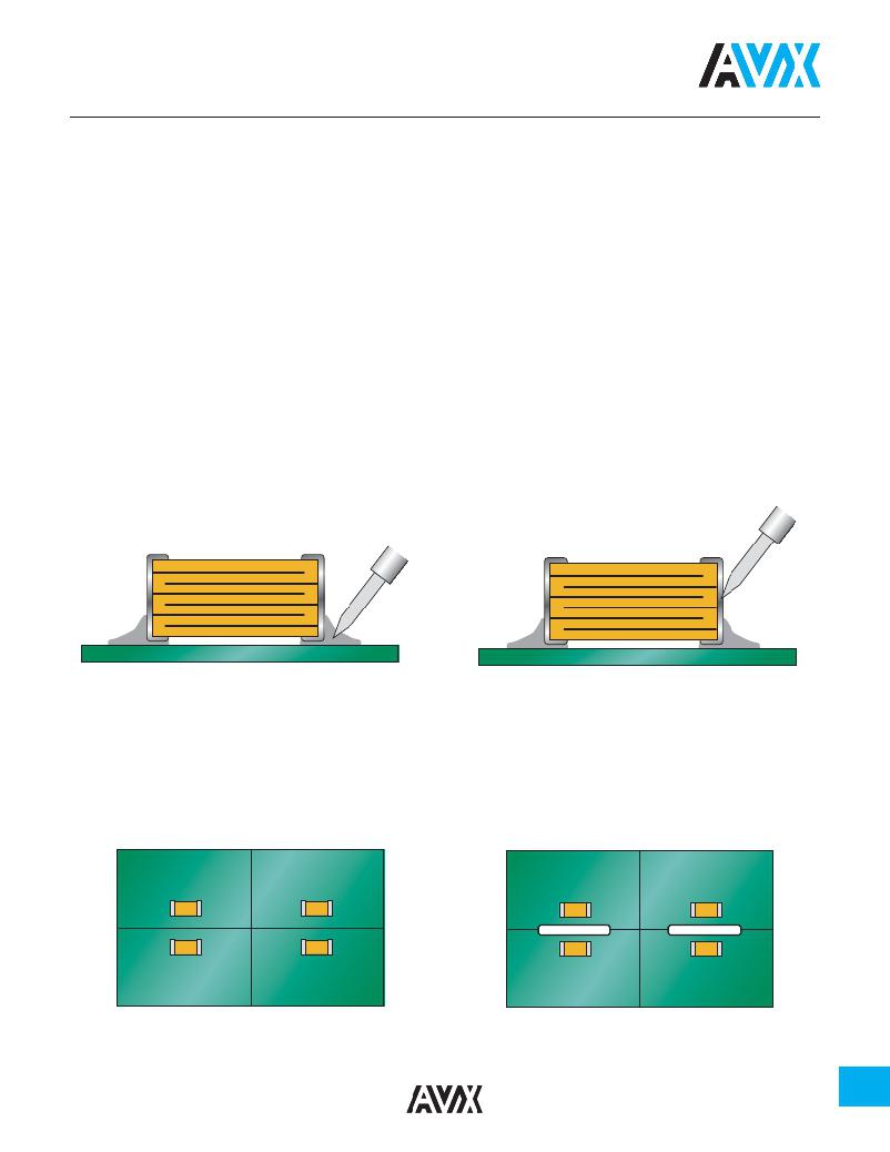
�Solder� Tip�
�Preferred� Method� -� No� Direct� Part� Contact�
�REWORKING� OF� MLCS�
�Thermal� shock� is� common� in� MLCs� that� are� manually�
�attached� or� reworked� with� a� soldering� iron.� AVX� strongly�
�recommends� that� any� reworking� of� MLCs� be� done� with� hot�
�air� reflow� rather� than� soldering� irons.� It� is� practically�
�impossible� to� cause� any� thermal� shock� in� ceramic�
�capacitors� when� using� hot� air� reflow.�
�However� direct� contact� by� the� soldering� iron� tip� often�
�causes� thermal� cracks� that� may� fail� at� a� later� date.� If� rework�
�by� soldering� iron� is� absolutely� necessary,� it� is� recommended�
�that� the� wattage� of� the� iron� be� less� than� 30� watts� and� the�
�tip� temperature� be� <300oC.� Rework� should� be� performed�
�by� applying� the� solder� iron� tip� to� the� pad� and� not� directly�
�contacting� any� part� of� the� ceramic� capacitor.�
�Solder� Tip�
�Poor� Method� -� Direct� Contact� with� Part�
�PCB� BOARD� DESIGN�
�To� avoid� many� of� the� handling� problems,� AVX� recommends� that� MLCs� be� located� at� least� .2"� away� from� nearest� edge� of� board.�
�However� when� this� is� not� possible,� AVX� recommends� that� the� panel� be� routed� along� the� cut� line,� adjacent� to� where� the� MLC� is�
�located.�
�No� Stress� Relief� for� MLCs�
�Routed� Cut� Line� Relieves� Stress� on� MLC�
�113�
�发布紧急采购,3分钟左右您将得到回复。
相关PDF资料
AVE477M10G24T-F
CAP ALUM 470UF 10V 20% SMD
AVEK337M10G24T-F
CAP ALUM 330UF 10V 20% SMD
AVES226M35D16T-F
CAP ALUM 22UF 35V 20% SMD
AVEZ476M35X16T-F
CAP ALUM 47UF 35V 20% SMD
AVRF107M35F24T-F
CAP ALUM 100UF 35V 20% SMD
AVS107M50G24B-F
CAP ALUM 100UF 50V 20% SMD
B048F160T24
BCM BUS CONVERTER 16V 240W
B048F320T30
BCM BUS CONVERTER 32V 300W
相关代理商/技术参数
AU016D104KAG2A-5K
功能描述:多层陶瓷电容器MLCC - SMD/SMT 100nF 10% 6.3 Volts Gold Flash RoHS:否 制造商:American Technical Ceramics (ATC) 电容:10 pF 容差:1 % 电压额定值:250 V 温度系数/代码:C0G (NP0) 外壳代码 - in:0505 外壳代码 - mm:1414 工作温度范围:- 55 C to + 125 C 产品:Low ESR MLCCs 封装:Reel
AU016D104MAG2A
功能描述:多层陶瓷电容器MLCC - SMD/SMT 6.3volts 0.1uF 20% X5R 0201 SIZE
RoHS:否 制造商:American Technical Ceramics (ATC) 电容:10 pF 容差:1 % 电压额定值:250 V 温度系数/代码:C0G (NP0) 外壳代码 - in:0505 外壳代码 - mm:1414 工作温度范围:- 55 C to + 125 C 产品:Low ESR MLCCs 封装:Reel
AU016D223KA72A
功能描述:多层陶瓷电容器MLCC - SMD/SMT 6.3volts 0.01uF 10% X5R 0201 SIZE
RoHS:否 制造商:American Technical Ceramics (ATC) 电容:10 pF 容差:1 % 电压额定值:250 V 温度系数/代码:C0G (NP0) 外壳代码 - in:0505 外壳代码 - mm:1414 工作温度范围:- 55 C to + 125 C 产品:Low ESR MLCCs 封装:Reel
AU016D223KAG2A
功能描述:多层陶瓷电容器MLCC - SMD/SMT 6.3volts 22000pF 10% X5R
RoHS:否 制造商:American Technical Ceramics (ATC) 电容:10 pF 容差:1 % 电压额定值:250 V 温度系数/代码:C0G (NP0) 外壳代码 - in:0505 外壳代码 - mm:1414 工作温度范围:- 55 C to + 125 C 产品:Low ESR MLCCs 封装:Reel
AU01A
制造商:Sanken Electric Co Ltd 功能描述:Pack 制造商:Sanken Electric Co Ltd 功能描述:Bulk
AU01AV
制造商:Sanken Electric Co Ltd 功能描述:DIODE FAST REC AXIAL
AU01AV0
制造商:Sanken Electric Co Ltd 功能描述:DIODE FAST REC AXIAL
AU01AV1
制造商:Sanken Electric Co Ltd 功能描述:DIODE FAST REC AXIAL